
Digital Logic Circuits
Learn how digital circuits select inputs, store state and move data through concepts and hands-on RTL examples.
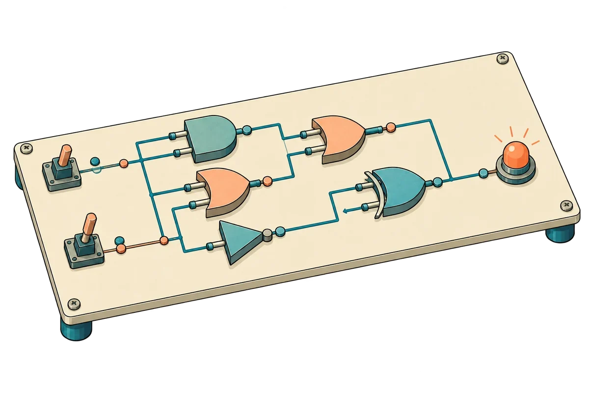
Das wirst du lernen
- Explain combinational circuits using binary numbers, gates and Boolean algebra
- Calculate adder, comparator and signed arithmetic boundary cases
- Implement a MUX, counter and shift register and compare waveforms
- Complete a small design using state machines, timing constraints and a verification plan
Bevor du beginnst
Lies die Konzepte im Browser. Bereite für die Übungen ein Digital Design Studio Desktop-Projekt und Ausführungsrechte vor. Quellcode und Eingabedateien sind enthalten.
Installation und erster Start ↗Lehrplan
- Foundations of digital logic
- Binary and hexadecimalKonzept
Represent the same value in binary and hexadecimal.
- Gates and truth tablesKonzept
Compare the output rules of AND, OR, NOT and XOR.
- Boolean algebra and De Morgan’s lawsKonzept
Check whether different expressions produce the same output.
- Decoders and enable signalsKonzept
Turn a binary address into one active output.
- Signals and selection
- Bits, signals and portsKonzept
Identify inputs, outputs and the meaning of one-bit values.
- Specify the selection with a truth tableKonzept
List every input combination and define its expected output.
- The MUX and its observation registerKonzept
Distinguish a combinational output from a sampled output.
- Write and run the RTL
- Describe a MUX with a conditional expressionKonzept
Connect the select signal and data inputs in RTL.
- MUX simulation labÜbung
Compare outputs using the provided source and input files.
- Interpret and check
- Input changes and sampling instantsKonzept
Track y and sampled_y before and after a clock edge.
- Test the cases that reveal mistakesKonzept
Choose cases that reveal reversed selection and sampling errors.
- MUX knowledge checkWissensprüfung
Check your understanding of selection and storage.
- Arithmetic circuits and state
- Half adders and full addersKonzept
Compute sum and carry separately, then chain them.
- Signed values and overflowKonzept
Interpret the same bits as unsigned and two’s complement.
- Comparators and boundary conditionsKonzept
Connect equality and magnitude comparisons to boundary tests.
- Flip-flops and clock enableKonzept
Specify the priority of reset, enable and hold.
- Numbers and time
- Bit width and binary valuesKonzept
Read the values and bit positions of a two-bit number.
- Clock edges and stateKonzept
Separate input changes from register updates.
- The counter and synchronous resetKonzept
Compute the next state from the previous state.
- Update state and run the lab
- Compute the next value from the old valueKonzept
Read nonblocking assignments and reset priority in the code.
- Counter simulation labÜbung
Observe incrementing and wraparound after reset.
- Boundaries and debugging
- What follows the maximum value?Konzept
Calculate addition beyond the register width.
- Diagnose reset and counting errorsKonzept
Check the initial value, reset and first edge in order.
- Counter knowledge checkWissensprüfung
Check bit width and wraparound behavior.
- Bits and data flow
- Vector direction and bit indicesKonzept
Read q[2:0] and identify the positions selected by a slice.
- Read a serial input over timeKonzept
Organize a stream of one-bit inputs into a timeline.
- State changes in a shift registerKonzept
Move the previous bits and insert the new input.
- Concatenation and the lab
- Slices and concatenationKonzept
Trace how concatenated bits map into the new register.
- Shift-register simulation labÜbung
Trace the serial input alongside q.
- Latency and debugging
- Follow a bit to the outputKonzept
Count the edges as one input bit moves through the stages.
- Check direction, reset and input orderKonzept
Use a single-bit pattern to expose reversed connections.
- Shift-register knowledge checkWissensprüfung
Compute the next state using the pre-update value.
- Connect and verify circuits
- Combinational delay and timing budgetsKonzept
Distinguish functional simulation from timing verification.
- Design a small state machineKonzept
Describe state, input and next state in a transition table.
- Verification plans and failure tracesKonzept
Define expected results for normal, boundary and reset cases.
- Capstone: serial pattern detectorKonzept
Design and check a state machine that detects the pattern 101.